Sun Valley Water & Wastewater Project
Piping Distribution & Pump Sizing
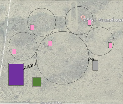
To determine the amount of piping that the systems would require on the site, the site plan was incorporated into BentleyFlowMaster. This was placed over an image of the site to give an indication of the scale of the dome houses and tanks in relation to the site. The final image is shown in Figure 9. This shows a zoomed in image of the dome houses and the storage tanks for the systems. The coloring of the items in Figure 9 are similar to those shown in the site plan in Figure 2. The pink boxes indicate the composting toilets, the purple box indicates the potable water storage tank, the green box indicates the rainwater harvesting barrel, and the gray box indicates graywater storage tank. The information provided in the pipe flex tables indicated that the total length of pipe that would be required was approximately 10 feet. This length was used to incorporate the cost of the piping for the water and wastewater systems.

Figure 9: Site plan of the dome houses and the tanks for each system with piping
The piping from the water storage tank to the home will be pumped with an average flow rate of approximately 6 gallons per minute (gpm). The pump curve provided in Appendix G demonstrated the approximate power required for this type of pump would need to be about 1/3 horsepower. The diameter for the piping was assumed using this same pump curve as well. It was assumed that 4” polyvinylchloride piping would be used for this system. The rainwater harvesting system will not require pumps or piping because the water will go directly from the gutter to the rain barrel. The graywater storage tank will have the same flow rate and thus power requirements as the potable water storage tank. Thus, a similar pump will be used for the graywater storage tank.


